Yes its a Sesame Street theme this week, although instead of me teaching basic vocabulary and how to count to 12 you are all going to get a lesson on early New York Central electric locomotives and DC motor control systems. Sounds fun doesn't it? The framing device for today's lesson comes in the form of a number of locomotives "preserved" in a forested flood plain south of Albany, NY. These locomotives belonged (or still belong) to the Mohawk Chapter NRHS which received them from Amtrak and Conrail sometime around 1980. The collection includes an ex-NYC, ex-PC, ex-Amtrak
Alco RS-3, an ex-NYC, ex-PC, ex-Conrail
General Electric U25B and two former Ney York Central electric locomotives. While RS-3s and U25's are great, the two electrics are the real gems here because not only are they quite old, they also represent about half the total number of ex-NYC electrics that have been preserved.
The first of these electrics is the only surviving
T-Motor, built as class T-3a in 1926 and represents the last batch of the second generation of NYC electric locomotive power. The second of these locomotives is
S-Motor #100, which isn't just a member of the first class of New York Central electrics, but is in fact the prototype for the first class of New York Central electrics and because the S-Motors were the first class of independent main line electric locomotives ever built
anywhere, #100 is the
world's first main line electric locomotive.
Now I know what you're thinking, wasn't the first main line railroad electrification built on the
B&O's Howard Street Tunnel in 1895? Well you would be right, but remember that that system was designed for electric assist of steam locomotives over a short stretch of steeply graded track with tunnels. Electrics would tow the steam engines, still fired up and making steam, through the short electrified section and then cut off to allow the steam hauled train on its way. The New York Central embarked on a much more ambitious scheme to both eliminate steam engine exhaust from its
Park Avenue Tunnel and build a Grand new downtown rail terminal completely below ground level, which would make any sort of steam locomotive, under load or tow, completely infeasible. The S-Motors were the locomotives initially designed for this task with #100 being constructed in 1904, two years before the start of electric operations, in order to be throughly tested by both
Alco (who built the locmotive) and GE (who supplied the propulsion system), on a test track in Schenectady, NY. #100 was originally assigned the class of L and the
number 6000 while undergoing this testing. When it was time to enter service with 34 additional sisters #100's class was changed to T-1 and the number changed to 3400. After a deadly derailment on the second day of electrified service exposed a design flaw, #100's class was changed again from T to S and she was given the number she wears to this day.
Anyway, enough with the Wikipedia summary, its time to get onto some photos. You can see the whole set
here (scroll down a bit), but I will actually urge you all to finish reading the remainder of the presentation here first. In fact you should start by viewing this little video tour of the two units. Inside some interesting items are obscured by darkness so reading the photo essay afterwards may help make things clearer.
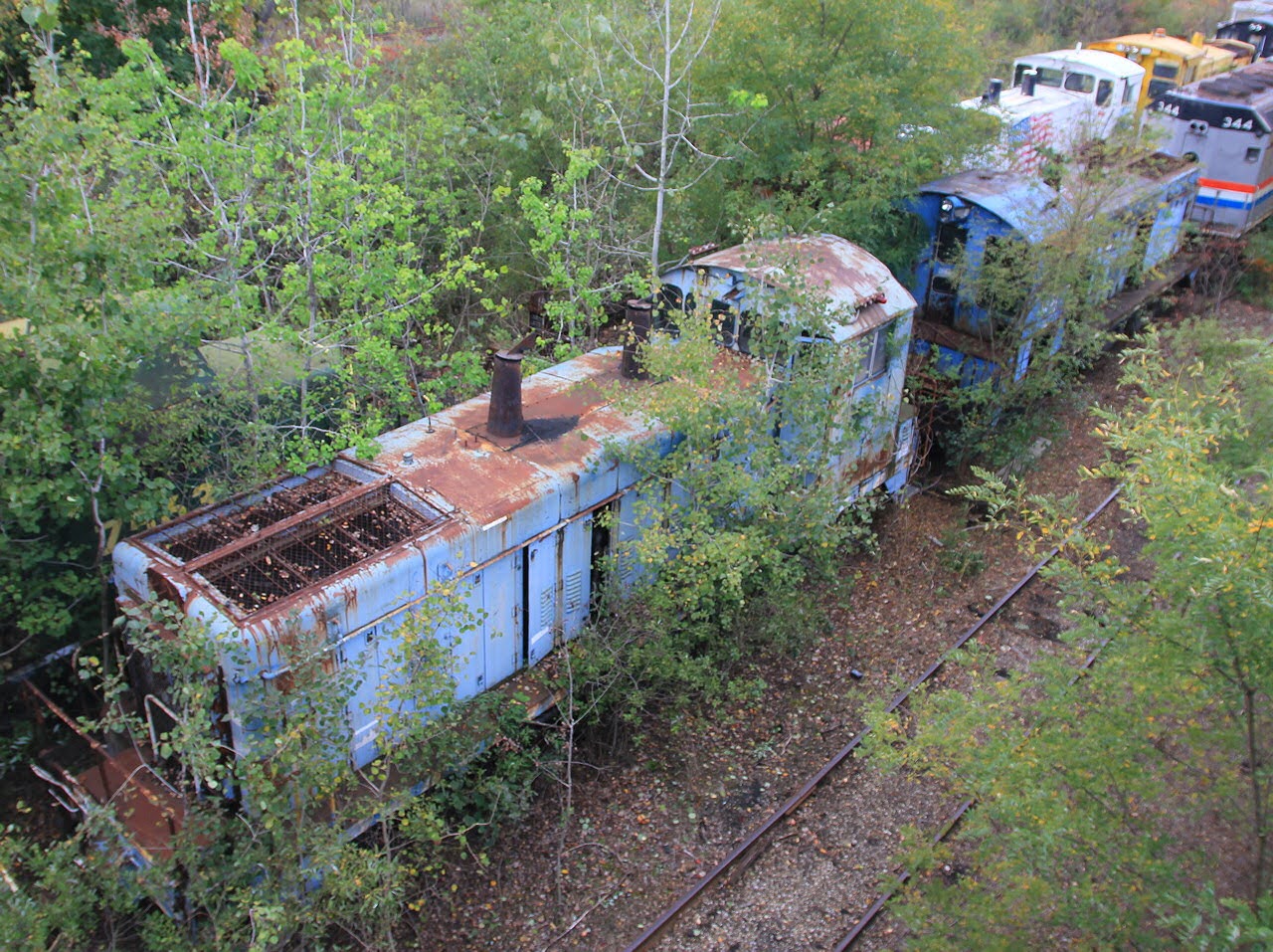
So how exactlyis the world's very first main line electric locomotive being treated these days? Climate controlled shed at a major railroad museum? Complete interior and exterior restoration with a goal of returning her to running condition? No, one of the most historic locomotives in the world is being left to sit out in the elements on an isolated spur track located within the Hudson River floodplain.
So whats going on here? As far as I have been able to determine the
Mohawk Chapter NRHS simply became defunct with their historic collection
left to fend for itself. Fortunately their collection is not located
where some landlord would care to threaten it with scrapping, but the
condition of all these locomotives is hardly ideal.
There
are some on again off again efforts to get people out there to at least
stabilize the units and I have been told that they have been purchased
by a heritage line in Massachusetts, but whomever the owner is getting
these locomotives out of their current location is going to take some
doing because even if the rail link to the former Conrail Albany
secondary is intact it is not passable without a good deal of rehab.
Whatever the state of the preservation efforts I wasn't going to pass up
the opportunity to tell the story behind these amazing relics from the
past.

The most apparent feature of the S-Motors are their short length,
however these units were not designed for switching, but for hauling
main line long distance passenger trains. The short length 39 feet was
seen as an advantage as it was half the length of a locomotive and
tender and trains could be doubleheaded without significant loss of
platform space. However they entered service a number of tracking
problems were identified and after 6 short years the units found
themselves relegated to secondary duties as the new T-Motors replacement
them.
The S-Motors were built with the 1-D-1 wheel configuration, which was
soon upgraded to 2-D-2 after the 1907 derailment. The driving wheels
were mounted on a rigid 4 axle frame with a suspension that was
primitive to say the least. Another problem with these early electrics
was that they made use of
"bi-polar" electric motors. No this does not mean that the motors would be full of energy one day and sluggish the next, but that the DC motor
armature
is mounted directly to the axle with two static electro-magnet "poles"
mounted to either side. This allowed the axle/armature combination to
move in the vertical plain as the wheel moved over bumps in the track.
unfortunately this axle/armature combination added to the units
Unpsring mass
that of course affected track handling and ride quality. As soon as
improved technology allowed the motors to be reduced in size, electric
locomotives switched to using geared motors and ultimately nose
suspended motors. Also in this photo note the
third rail pickup shoe fuse box rated at 700 amps.
Squeezed in front of the 4 driving axles on each end of the unit are two, twin axle
pony trucks.
These were originally a single axle truck, but after the 1906
derailment it was determined that the 1-D-1 design was not sufficiently
stable at high speed. The single S-1 and her 34 S-2 sisters were
modified to fit the new 2 axle design. The later 12 units of the S-3
class built in 1909 were lengthened by 4 feet to better fit it.
Unfortunately, in solving the stability problem the extra pony axles
took even more weight off the drivers and resulted in poor starting
characteristics, especially with long trains.
Another neat 1904 feature on the S-motors are the use of
friction bearings on the main driving axles. Virtually unheard of today on modern railroads, friction, aka plain, bearings make use of a consumable oil supply to lubricate the action of a round steel axle rotating in a plain soft metal semi-circle. The oil would create a hydrodynamic boundary layer between the axle and the
Babbitt metal of the bearing that would prevent the two parts from physically touching. The oil was applied to the rotating axle via a
pad at the bottom of the journal box, which had a reservoir of oil it that was wicked up through the pad.
Well that's enough for the exterior of #100, let's head
inside and see what we can find. The unique design of the S-Motor is sort of a rich man's
Steeplecab,
clearly inspired by the latter, but with a bit more fit and finish for
its main line assignments. Compared to s Staplecab design, the cab
space of an S-Motor was a lot more spacious to fit both a
larger air compressor
and a train heating boiler required for passenger service. Here we
stand inside the cab area looking toward the #2 end. The S-Motor was
designed for both a engineer and fireman with each position being on the
accustomed side.

The control stand of an S-Motor should be familiar to anyone who has
visited a trolley museum as the technology behind it is basically the
same, only a little bit more fancy. Acceleration of the S-Motor is
completely manual in that the engineer does not select an acceleration
rate (as one does on more modern electrics), but instead has direct
control over the amount of voltage going to the motors. In a DC motor
control system rotational speed of the motor is dependent upon the
voltage supplied. As the controller is advanced resistance is cut out
of the circuit applying more voltage to the motor. The large number of
notches on the controlled is to allow the engineer to make small
adjustments to the voltage in order to create a smooth acceleration
profile, avoid wheel slip and to avoid stalling the wheels and burning
out the windings. Today such tasks are automated by camshaft
controllers in DC propulsion systems or software in AC systems.
This
control system would also make use of series and parallel wiring to
increase efficiency by negating the need to dump power into heat through
the resistance elements. With motors connected in series seeing the
total voltage drop split between them so at 660 volts DC from the third
rail, 4 motors connected in series would each see a voltage of 165
volts, two motors in series 330 and all 4 motors in parallel the full
660 volts. I am not sure how those modes are engaged, either
automatically as one notches up the controller or via a separate
mechanism, but such a system has been part of DC systems since Thomas
Edison.
Also seen here at the engineer's station is
the instrument cluster including gauges for air pressure and DC amps
running through the motor. The S-Motors were fitted with 4 GE model 84
electric motors rated for 550hp maximum output giving the S's a total of
2200hp starting power, which put them towards the upper end of
contemporary steam passenger trains in terms of power. The continuous
rating was 1700hp.
The fireman's side is a bit more spartan featuring only an emergency
brake valve. Note the New York Central green interior which later went
on to become Penn Central Green.
If there was one thing that was not in short supply in these electrics
it was heaters. The cab was full of resistance heaters which I guess
implied that New York City still used to see "winters" back a century
ago.
Heavy load auxiliary items like the air compressor and cab heaters were controlled from these breaker-switches.


